





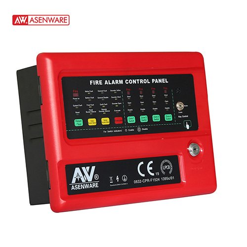
The conventional 4-zone fire alarm control panel is the central component of a conventional fire alarm system. It is designed for applications requiring a smoke detector, siren, manual call points, and monitoring of an automatic water sprinkler system. Each zone can be deactivated with a button. The basic unit offers 1 to 8 trigger zones, and up to 32 zones for larger installations.
Specifications of the conventional 4-zone fire alarm control panel:
- This is a modular design; the panel can easily expand from 1 zone to 32 zones.
- 2-level control mode via locking
- 24V DC and 5V DC power output.
- Output of FIRE and FAULT signals.
- 2 general siren activations.
- Each zone has 1 input for circuit detectors
- Each zone can be deactivated by a button.
- RESET button to reset the panel.
- SILENCE button to stop the BUZZER and SOUNDS.
- EVACUATE button to immediately trigger a manual fire alarm.
- Battery undervoltage protection function: activates when the battery voltage is below 21V DC.
- The battery will be automatically shut off until mains power is restored.
- Optional GSM module for fire alarm via SMS
| CA ENTRANCE | 220 V CA 50 Hz |
| CC EXIT | 24V DC typical |
| Microcontroller supply voltage | 5V for the microcontroller power supply board, 3.3V for the other components. |
| 24V DC current from the PSE | standby current of 450 mA |
| Maximum current from the PSE | 2A except for battery charging |
| Current Batteries | 1.85 A maximum, current limited |
| Auxiliary output | 24 V DC ± 10%, 100 mA max, current limited, monitored |
| Batteries | 2*12V/2.3Ah sealed gel lead-acid battery, self-regulating |
| 2 x 12V / 7Ah if necessary | |
| Battery replacement resistor | 2Ω ±10% if necessary |
| Battery undervoltage protection | 22.2V |
| Connecting the detectors allowed each zone to connect. | 20 (except MCP) |
| zone alarm current | 6 mA minimum / 27 mA maximum |
| exit of the bell ringer | 2 x 0,75 A maximum |
| fire protection | 100 mA maximum |
| Fire router | 100 mA maximum |
| Fault routing | 100 mA maximum |
| Communication protocol | 2-wire RS485 bus system |
| Relay contact rating | Secondary contacts (NO/NC) 1 A at 24 V DC |
| EOL resistance for zone | 6,8 kΩ 1 W |
| End-of-line resistor for outputs | 6,8 kΩ 1 W |
| Fuse on the power supply board | 3A/250V, 20mm Glass Tube Fuse |
| Fuse on the EMI board | Glass tube fuse 1 A / 250 V, 20 mm |
| Environment | Class A temperature range: -5 to 50 °C; Humidity: 5 to 95% RH, non-condensing |
| Terminal block gauge | All terminals are designed for cable cross-sections of 12 to 18 AWG (0.75 to 2.5 mm²). |

Avis
Il n’y a pas encore d’avis.